I started thinking about this after I picked up a s/h stepper valve and controller and I wondered whether a programmable microprocessor control is really necessary on a basic carburetted motor, especially when I've got the little LED lambda display I already built, I figured there ought to be a way to drive the stepper from the display output lines "the old fashioned way", in other words using TTL (transistor transistor logic).
So here's what I've come up with.
The motor appears to be a two phase bipolar design, so I originally looked at using a shift register and a couple of H bridges to control it, but then I saw there are some pre-made little stepper driver modules available for about £2.50. So that's a no-brainer and I immediately ordered one.
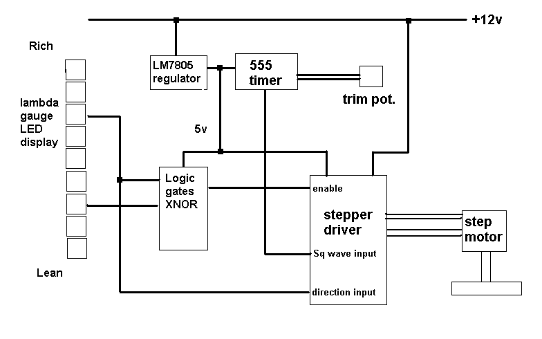
The driver module has three main control inputs, one dictates the step rate of the motor providing one step each time the input goes between high and low, the second is also a high/low trigger which changes the direction of the motor, one way is high the other way is low, and the third disables the motor drive when a logic low input is applied.
So below is my schematic - the 555 chip provides a square wave to the step input and can be adjusted from about 0.5 Hz right up to stupid fast (note, I know the schematic is incomplete there needs to be some capacitors and a few other things to make this all work).
So that's half a second per step, not per revolution. I don't know the step angle of the motor yet but half a second per step ought to be way slow enough that damping the loop is well within range.
The gauge lights the display by grounding the cathodes of the LEDs. So I figure each LED connection can provide a logic low signal when the LED goes on. Using two chosen LEDs at appropriate points in the lean to rich scale I need to drive the motor one way when the chosen "lean" LED goes out, and drive it the other way when the chosen "rich" LED comes on. In between these points I need the motor to stop.
The connection from the "rich" LED means the direction pin of the driver module ought to see a logic high when the "rich" LED is off (if it doesn't I'll have to add a pull-up resistor), and then a logic low when that LED comes on to reverse the motor direction.
To stop the motor when the mixture is anywhere in between the two LEDs I think I can use an XNOR logic gate. That will provide a logic high when both LEDs are either on or off together (so the motor is enabled in those conditions) and a logic low when only one of the LEDs is on; which will be the "lean" LED in practice (so the motor is disabled when the mixture is showing between the two LEDs).
In case the motor doesn't respond quickly enough, apart from increasing the 555 frequency, I could also add some additional connections from adjacent LED bases to run the motor in half step mode on marginal mixture conditions and full step on more severe deviations (so the motor spins faster as the mixture goes further out of range).
Anyway, here it is, bonkers right ?
 You'd be able to build in 'if' statements to detect conditions such as startup and drift very easily.

