
lpg feed pipe size on 500 bhp engine.
Re: lpg feed pipe size on 500 bhp engine.
well spotted Brian thank you
"The Temptress" thread..... https://forum.retro-rides.org/thread/215234/temptress
'Medusa" thread .....https://www.rodsnsods.co.uk/threads/medusa.206057/
'Medusa" thread .....https://www.rodsnsods.co.uk/threads/medusa.206057/
Re: lpg feed pipe size on 500 bhp engine.
right another bundle of nonsensical questions...
my reducers have this threaded hole in the side for the gas to go in ..

i have one solenoid that fits ..

but its a 8mmm, and everything feeding the reducers is 6mm .
i also have these ..


which are the 6mm screw in stubs off the omvl r90's .

they screw into the prins reducers , and will butt up against the end of their threads ,can i loctite these in and have no leaks , or is that a really terrible idea,i assumed it was but someone may nah , that's fine i had no problems so thought i would ask....
actually i just realised , if i can find a nut the same thread i can simply locknut them with a copper washer .
next question is , i have to mount the injectors under the manifolds ,can they work with the outlet nozzles pointing vertically upwards ? i suppose i could mount them horizontally too , with the nozzles pointing at the side of the engine.
lastly , whats the longest the pipes to each inlet can be and not be pooh?
good news is i have a functioning crank sensor , and i fixed the siezed reducer like so ..
drilled little hole ..

knocked out piston and spring ..

tapped hole..

loctited in screw .

trimmed excess ..

job done.
regards
robert
my reducers have this threaded hole in the side for the gas to go in ..
i have one solenoid that fits ..
but its a 8mmm, and everything feeding the reducers is 6mm .
i also have these ..
which are the 6mm screw in stubs off the omvl r90's .
they screw into the prins reducers , and will butt up against the end of their threads ,can i loctite these in and have no leaks , or is that a really terrible idea,i assumed it was but someone may nah , that's fine i had no problems so thought i would ask....
actually i just realised , if i can find a nut the same thread i can simply locknut them with a copper washer .
next question is , i have to mount the injectors under the manifolds ,can they work with the outlet nozzles pointing vertically upwards ? i suppose i could mount them horizontally too , with the nozzles pointing at the side of the engine.
lastly , whats the longest the pipes to each inlet can be and not be pooh?
good news is i have a functioning crank sensor , and i fixed the siezed reducer like so ..
drilled little hole ..
knocked out piston and spring ..
tapped hole..
loctited in screw .
trimmed excess ..
job done.
regards
robert
"The Temptress" thread..... https://forum.retro-rides.org/thread/215234/temptress
'Medusa" thread .....https://www.rodsnsods.co.uk/threads/medusa.206057/
'Medusa" thread .....https://www.rodsnsods.co.uk/threads/medusa.206057/
Re: lpg feed pipe size on 500 bhp engine.
hmmm , well it looks like i can put the rail on its side ..
https://www.remixbg.com/Documentation/D ... 1_3_EN.pdf
https://www.remixbg.com/Documentation/D ... 1_3_EN.pdf
"The Temptress" thread..... https://forum.retro-rides.org/thread/215234/temptress
'Medusa" thread .....https://www.rodsnsods.co.uk/threads/medusa.206057/
'Medusa" thread .....https://www.rodsnsods.co.uk/threads/medusa.206057/
Re: lpg feed pipe size on 500 bhp engine.
Sorry the slow replies, so much work on.
Really would be best to use same injectors on both engines, likely a bad idea to mix and match especially on the same engine / cylinder bank.
Injectors work best when the plunger is pulled straight down, not too bad being horizontal but would never fit them upside down.
In case this helps swing your decision on injectors the OMVL injectors Bri talked about have side outlets (so might help with orientation of plunger throw), though ideally I think for your engines it would be better to fit single injectors with very short pipe runs between injectors and manifolds but if you must use injectors on rails keep pipe lengths short. Also, since the MJ will probably only run the engines in group injection mode it'll be better to fit injectors that are comparatively quite linear / fast to open and on a cost to linearity scale OMVL SL's are very good.. but are not available as single injectors. If I were to decide on what injectors to use for this project I would fit single MJ injectors.
Even your long inlet trumpets are comparatively short compared to an engine with an intake plenum. You might want to use manifold brass gas inlets that have a side opening so gas exits the 'spud' at 90 degrees to the orientation of the spud so pushes gas toward the inlet valves. Most suppliers sell this type, there's an indent on top of the spud that is aligned with the angle of gas outlet so you screw the spud in until outlet faces the inlet valve and secure it with Loctite.
Speaking of Loctite, there are far better potions for sealing gas joints. The best I've ever used is sold by TinleyTech, white silicone thread sealant stuff that works even where PTFE tape and sealing pastes won't, I'd mention the name but there doesn't seem to be a brand name on it, just some writing in German that spells out it's purpose. Not necessary for the spuds but would advise using this stuff on the threads of the reducer inlet.
There are many ways of getting from 6mm pipe feed to 8mm for the gas inlet, a simple and cheap inline 6mm to 8mm adaptor might best suit your purpose but you would need a short length of 8mm copper pipe.
Simon
Really would be best to use same injectors on both engines, likely a bad idea to mix and match especially on the same engine / cylinder bank.
Injectors work best when the plunger is pulled straight down, not too bad being horizontal but would never fit them upside down.
In case this helps swing your decision on injectors the OMVL injectors Bri talked about have side outlets (so might help with orientation of plunger throw), though ideally I think for your engines it would be better to fit single injectors with very short pipe runs between injectors and manifolds but if you must use injectors on rails keep pipe lengths short. Also, since the MJ will probably only run the engines in group injection mode it'll be better to fit injectors that are comparatively quite linear / fast to open and on a cost to linearity scale OMVL SL's are very good.. but are not available as single injectors. If I were to decide on what injectors to use for this project I would fit single MJ injectors.
Even your long inlet trumpets are comparatively short compared to an engine with an intake plenum. You might want to use manifold brass gas inlets that have a side opening so gas exits the 'spud' at 90 degrees to the orientation of the spud so pushes gas toward the inlet valves. Most suppliers sell this type, there's an indent on top of the spud that is aligned with the angle of gas outlet so you screw the spud in until outlet faces the inlet valve and secure it with Loctite.
Speaking of Loctite, there are far better potions for sealing gas joints. The best I've ever used is sold by TinleyTech, white silicone thread sealant stuff that works even where PTFE tape and sealing pastes won't, I'd mention the name but there doesn't seem to be a brand name on it, just some writing in German that spells out it's purpose. Not necessary for the spuds but would advise using this stuff on the threads of the reducer inlet.
There are many ways of getting from 6mm pipe feed to 8mm for the gas inlet, a simple and cheap inline 6mm to 8mm adaptor might best suit your purpose but you would need a short length of 8mm copper pipe.
Simon
Full time LPG installer
Servicing / Diagnostics / Repairs to all systems / DIY conversion kits supplied with thorough tech support
Mid Yorkshire
2 miles A1, 8 miles M62,
http://www.Lpgc.co.uk
Twitter https://twitter.com/AutogasSimon
07816237240
Servicing / Diagnostics / Repairs to all systems / DIY conversion kits supplied with thorough tech support
Mid Yorkshire
2 miles A1, 8 miles M62,
http://www.Lpgc.co.uk
Twitter https://twitter.com/AutogasSimon
07816237240
Re: lpg feed pipe size on 500 bhp engine.
thank you Simon , much appreciated ,i will check out that thread sealant from tinley tech . i find that i have a 8mm to 6mm reducer , so for one of the reducers i can simply use the 8mm solenoid .
i have found some brc orange injectors
https://www.ebay.co.uk/itm/Injection-Ra ... 3203792935
i researched them and they appear to be 70 quid each new (so i guess they are good quality).. ,and go up to 45 bhp / cylinder , i got them for 30 quid so thought it worth a go .Good thing is they are in two blocks of 3 , so i can space them out to get the feed pipes short .the other engine will use the matrix injectors , and they are also in two blocks so i can space those out as well.
wit this megasquirt i can put in two maps for fueling ,and two sets of injector specs , to cater for their differing ohms etc . i am stuck on the same ignition timing table ,however the two engines are not that far apart in spec , the inlet cam on the 3.6 being the only major difference .
i now have to source hose for the injectors ,and clips , and also same for the reducer feeds ,oh and a filter .. i have a prins filter with a sensor in the top for temp pressure , so i will use that for one engine , i wish they would design it all at 12mm or 16mm , and not mix the sizes though !
Th ecu will be firing the injectors in a single batch fire on each engine , since i only have 2 output channels , however i do have the option of 1.2. or 4 squirts per revolution ,and also alternating between banks or simultaneous.
i have 2 old msd boxes i can fire with the ecu too , so i can open up the plug gaps a bit and get multi spark ignition .
i know its not ideal , but i think i should get an improvement over the mixers with the air rushing past the bellmouths messing it all up .
regards
robert
i have found some brc orange injectors
https://www.ebay.co.uk/itm/Injection-Ra ... 3203792935
i researched them and they appear to be 70 quid each new (so i guess they are good quality).. ,and go up to 45 bhp / cylinder , i got them for 30 quid so thought it worth a go .Good thing is they are in two blocks of 3 , so i can space them out to get the feed pipes short .the other engine will use the matrix injectors , and they are also in two blocks so i can space those out as well.
wit this megasquirt i can put in two maps for fueling ,and two sets of injector specs , to cater for their differing ohms etc . i am stuck on the same ignition timing table ,however the two engines are not that far apart in spec , the inlet cam on the 3.6 being the only major difference .
i now have to source hose for the injectors ,and clips , and also same for the reducer feeds ,oh and a filter .. i have a prins filter with a sensor in the top for temp pressure , so i will use that for one engine , i wish they would design it all at 12mm or 16mm , and not mix the sizes though !
Th ecu will be firing the injectors in a single batch fire on each engine , since i only have 2 output channels , however i do have the option of 1.2. or 4 squirts per revolution ,and also alternating between banks or simultaneous.
i have 2 old msd boxes i can fire with the ecu too , so i can open up the plug gaps a bit and get multi spark ignition .
i know its not ideal , but i think i should get an improvement over the mixers with the air rushing past the bellmouths messing it all up .
regards
robert
"The Temptress" thread..... https://forum.retro-rides.org/thread/215234/temptress
'Medusa" thread .....https://www.rodsnsods.co.uk/threads/medusa.206057/
'Medusa" thread .....https://www.rodsnsods.co.uk/threads/medusa.206057/
Re: lpg feed pipe size on 500 bhp engine.
Easiest option to get between 12mm and 16mm is to buy a filter with the outlets you want to convert between. Just be glad your not dealing with anything using the 14mm size that Landi used for some reason, even finding the pipe to fit that properly was a pain.
Re: lpg feed pipe size on 500 bhp engine.
The Prins filter is usually 16 to 12mm anyway... But depending on how it's piped up and what reducer(s) is/are used there might still be the need to get from 16mm to 12mm pipe... Inline adaptors are available to get from just about any pipe to any pipe.
Rob if I understand you correctly your MS has 2 injector channel outputs, you can set different maps for each channel so you plan on using 1 channel for 1 engine and the other channel for the other engine...which is the only way given engines are different size and you plan on using different injectors on each. All considered would advise using 1 injection pulse per revolution, which is still twice as often pulses as sequential injection (which is 1 pulse per engine/intake/cam cycle so 1 pulse every 2 engine revolutions) so is equal regularity of pulses as group injection. I say this because more often pulses would very likely be a problem especially at higher rpms due to LPG injector latency which even with great LPG injectors is still much higher than petrol injector latency.
I still have reservations about the setup... On a 4 cyl engine if you used both channels of the MS you could wire injectors for cyl 1 & 4 to one channel and 3 & 2 to the other channel and due to firing injectors once per rev (twice per intake cycle) everything would balance out, but everything may not balance out on a 6 cyl with all 6 cyl injectors firing at the same time (moment inlet valve opens compared to moment the injector fires) and any ill effects from this may be exaggerated by the lack of a plenum. You can get around the 'balance' problem by increasing frequency of injection pulses per engine revolution but then injector latency becomes a greater percentage of available injection window... So, say if you set injection to 2 pulses per revolution it would help equalling (balancing) injection timing compared to inlet valve opening moment and this may raise hopes when calibrating idle fuelling. But then at only 1500 rpm the LPG injectors would be opening and closing as fast as they would be on a sequential setup at 6000rpm and injector latency (say 2ms for the BRC) would already be quite a high percentage of available window (20ms for a sequential system at 6000rpm so latencu at only 1500rpm equal to 10%)... At 6000rpm with the 2 pulses per rev setup latency would be 8ms out of the 20ms so 40% of injection pulse duration would be just to cover the latency. Latency can be considered injector dead time so If you lose 40% of window due to latency you have to run a correspondingly higher nozzle size or pressure and then you have problems with injector response / latency at low loads because you still have the same pressure and nozzle size combination that will fuel the engine correctly at full load at high rpm even with the latency but at low loads the injectors only have to pulse for very small duration and perhaps below the minimum they can accurately meter gas at - If an injector has latency of 2ms and for idle the injector would only have to pulse for 1.9ms total including the latency time it becomes a problem for mapping.
Rob if I understand you correctly your MS has 2 injector channel outputs, you can set different maps for each channel so you plan on using 1 channel for 1 engine and the other channel for the other engine...which is the only way given engines are different size and you plan on using different injectors on each. All considered would advise using 1 injection pulse per revolution, which is still twice as often pulses as sequential injection (which is 1 pulse per engine/intake/cam cycle so 1 pulse every 2 engine revolutions) so is equal regularity of pulses as group injection. I say this because more often pulses would very likely be a problem especially at higher rpms due to LPG injector latency which even with great LPG injectors is still much higher than petrol injector latency.
I still have reservations about the setup... On a 4 cyl engine if you used both channels of the MS you could wire injectors for cyl 1 & 4 to one channel and 3 & 2 to the other channel and due to firing injectors once per rev (twice per intake cycle) everything would balance out, but everything may not balance out on a 6 cyl with all 6 cyl injectors firing at the same time (moment inlet valve opens compared to moment the injector fires) and any ill effects from this may be exaggerated by the lack of a plenum. You can get around the 'balance' problem by increasing frequency of injection pulses per engine revolution but then injector latency becomes a greater percentage of available injection window... So, say if you set injection to 2 pulses per revolution it would help equalling (balancing) injection timing compared to inlet valve opening moment and this may raise hopes when calibrating idle fuelling. But then at only 1500 rpm the LPG injectors would be opening and closing as fast as they would be on a sequential setup at 6000rpm and injector latency (say 2ms for the BRC) would already be quite a high percentage of available window (20ms for a sequential system at 6000rpm so latencu at only 1500rpm equal to 10%)... At 6000rpm with the 2 pulses per rev setup latency would be 8ms out of the 20ms so 40% of injection pulse duration would be just to cover the latency. Latency can be considered injector dead time so If you lose 40% of window due to latency you have to run a correspondingly higher nozzle size or pressure and then you have problems with injector response / latency at low loads because you still have the same pressure and nozzle size combination that will fuel the engine correctly at full load at high rpm even with the latency but at low loads the injectors only have to pulse for very small duration and perhaps below the minimum they can accurately meter gas at - If an injector has latency of 2ms and for idle the injector would only have to pulse for 1.9ms total including the latency time it becomes a problem for mapping.
Full time LPG installer
Servicing / Diagnostics / Repairs to all systems / DIY conversion kits supplied with thorough tech support
Mid Yorkshire
2 miles A1, 8 miles M62,
http://www.Lpgc.co.uk
Twitter https://twitter.com/AutogasSimon
07816237240
Servicing / Diagnostics / Repairs to all systems / DIY conversion kits supplied with thorough tech support
Mid Yorkshire
2 miles A1, 8 miles M62,
http://www.Lpgc.co.uk
Twitter https://twitter.com/AutogasSimon
07816237240
Re: lpg feed pipe size on 500 bhp engine.
good points simon , thank you , and thank you brian a filter is prob the easiest way .
re injection , i only have the astra to go by , its at around 45 bhp/cylinder , with the 3 ohm valteks on 4mm nozzles , i had 90% duty cycle on 2 squirts alternating ...with the kei hins i don't know my duty cycle , they are 1.5 ohms , and i drilled them to 3mm. map numbers definately bigger ...only difference i notice is its smoother on the afr readings ,and seems a bit faster .tickover is definately more stable , so i imagine the valteks were being really pushed to control things down low .
with this project , i think dai said the matrix are good for 250 bhp for 4 , and the brc are at the 45 bhp/cyl , so should both supply enough at the top end , the inlet stubs i am using are the original throttle body vacuum stubs , ,and i measured these at 3.3 mm dia. so the numbers all seem fairly similar the astra .
time will tell !
regards
robert
re injection , i only have the astra to go by , its at around 45 bhp/cylinder , with the 3 ohm valteks on 4mm nozzles , i had 90% duty cycle on 2 squirts alternating ...with the kei hins i don't know my duty cycle , they are 1.5 ohms , and i drilled them to 3mm. map numbers definately bigger ...only difference i notice is its smoother on the afr readings ,and seems a bit faster .tickover is definately more stable , so i imagine the valteks were being really pushed to control things down low .
with this project , i think dai said the matrix are good for 250 bhp for 4 , and the brc are at the 45 bhp/cyl , so should both supply enough at the top end , the inlet stubs i am using are the original throttle body vacuum stubs , ,and i measured these at 3.3 mm dia. so the numbers all seem fairly similar the astra .
time will tell !
regards
robert
"The Temptress" thread..... https://forum.retro-rides.org/thread/215234/temptress
'Medusa" thread .....https://www.rodsnsods.co.uk/threads/medusa.206057/
'Medusa" thread .....https://www.rodsnsods.co.uk/threads/medusa.206057/
Re: lpg feed pipe size on 500 bhp engine.
so bit of progress ,first reducer fitted and plumbed in ,all bits needed bought and arriving ,injectors arrived yesterday ..
and onto Injector settings ..
https://www.drive-and-save.com/content/ ... ctoren.pdf
from this i find this ..

So thats a zero dead time ? 4.9 ohms resistance on these ones.
Re the new injectors , they measure between 2 and 2.5 ohms , and i found this..

They got the ohms wrong but the sketch and pat number match , so that’s 0.8ms dead time ?
Eg..

RR
and onto Injector settings ..
https://www.drive-and-save.com/content/ ... ctoren.pdf
from this i find this ..
So thats a zero dead time ? 4.9 ohms resistance on these ones.
Re the new injectors , they measure between 2 and 2.5 ohms , and i found this..
They got the ohms wrong but the sketch and pat number match , so that’s 0.8ms dead time ?
Eg..
RR
"The Temptress" thread..... https://forum.retro-rides.org/thread/215234/temptress
'Medusa" thread .....https://www.rodsnsods.co.uk/threads/medusa.206057/
'Medusa" thread .....https://www.rodsnsods.co.uk/threads/medusa.206057/
Re: lpg feed pipe size on 500 bhp engine.
new injectors ,i didn't realise these are 70 quid each on the net , 30 for 6 seems a good bargain , they were badly listed on ebay .time will tell if they are any good .fingers crossed .
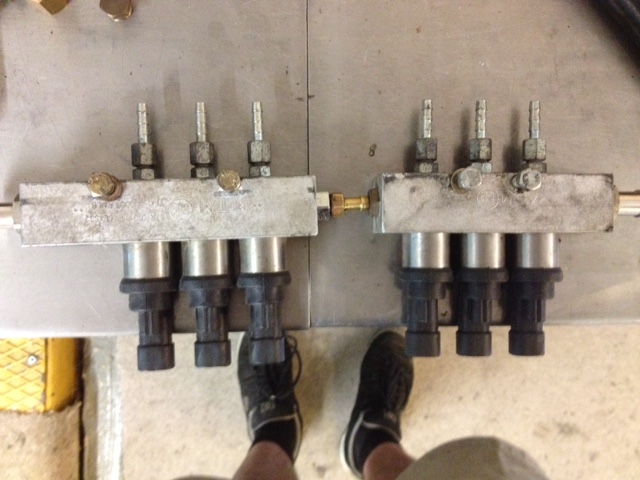
needless to say they have yet another variation on the "lets make a weird abstract plug design " game , with two thin pins seven miles down a hole ..so i will probably make up little slide on things ,and silicone them in there , like i had to do on the astra .
found some nice old bits.
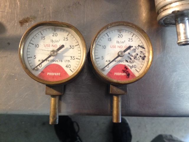
which with a bit of panel beating and polishing came up ok..
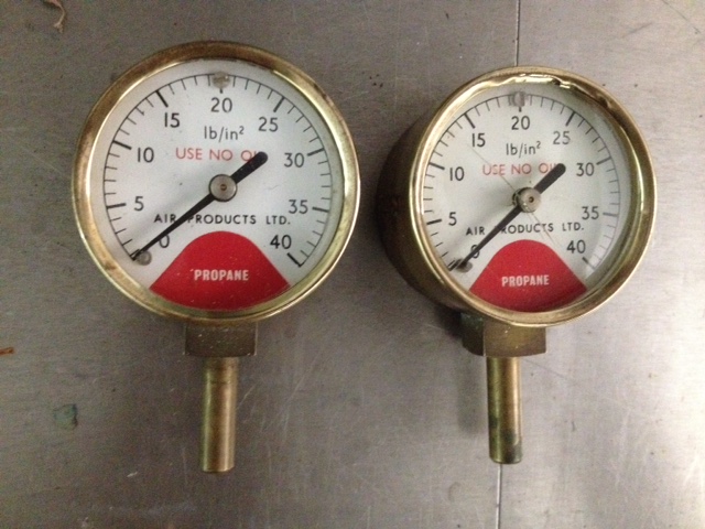
so i engineered the rails to have a take off for a gauge each , noice.
the new injectors have another weird plug on the temp sensor ..

honestly ! i mean ....really !! as if life wasn't complicated enough .
got engine 2 inj plumbed in yesterday , today i fit the reducer and inj to engine no1.
regards
robert
needless to say they have yet another variation on the "lets make a weird abstract plug design " game , with two thin pins seven miles down a hole ..so i will probably make up little slide on things ,and silicone them in there , like i had to do on the astra .
found some nice old bits.
which with a bit of panel beating and polishing came up ok..
so i engineered the rails to have a take off for a gauge each , noice.
the new injectors have another weird plug on the temp sensor ..
honestly ! i mean ....really !! as if life wasn't complicated enough .
got engine 2 inj plumbed in yesterday , today i fit the reducer and inj to engine no1.
regards
robert
"The Temptress" thread..... https://forum.retro-rides.org/thread/215234/temptress
'Medusa" thread .....https://www.rodsnsods.co.uk/threads/medusa.206057/
'Medusa" thread .....https://www.rodsnsods.co.uk/threads/medusa.206057/
Re: lpg feed pipe size on 500 bhp engine.
I think the response times for the Matrix injectors are slightly optimistic at 0.8ms, they're still very quick but probably closer to 1.2ms.
BRC 'normal type' like yours a bit pessimistic but not by much, they seem to dose fuel linearly down to about 3ms anyway.
Wouldn't even entertain the Rail or BRC GP13 injectors, very slow.
There can be a big difference between what response rates suggest and injector linearity at low pulse durations, close to the minimum response time they're not nearly as accurate or linear as at say minimum response rate plus 3ms. In the constant 200hz test results you showed above the pulse width was always the same and gas flow seemed to peak at half pulse width then hold steady for the rest of the pulse then almost immediately stop when the pulse stopped.. got to wonder then why they didn't show readings for 300hz? I think in reality gas flow would still be climbing toward the end of the electrical pulse and take longer to drop off at the end of the pulse.
Also worth mentioning that response times vary with temperature and pressure. Cold injectors are generally a bit slower even though cold coil windings will have lower electrical resistance so injectors will be pulled open by a stronger magnetic force. Higher pressure difference between gas and manifold can slow injector opening time, magnetic force must overcome both the spring and gas pressure that's holding the injector shut. High pressure and cold can have a cumulative effect, on some high performance engines I've converted it's been necessary to enable injector pre-heating for cold weather conditions (which pulses gas injectors before opening gas solenoids to heat the injectors and get them moving before switching to gas) but I don't think you'll need to be concerned about that.
BRC 'normal type' like yours a bit pessimistic but not by much, they seem to dose fuel linearly down to about 3ms anyway.
Wouldn't even entertain the Rail or BRC GP13 injectors, very slow.
There can be a big difference between what response rates suggest and injector linearity at low pulse durations, close to the minimum response time they're not nearly as accurate or linear as at say minimum response rate plus 3ms. In the constant 200hz test results you showed above the pulse width was always the same and gas flow seemed to peak at half pulse width then hold steady for the rest of the pulse then almost immediately stop when the pulse stopped.. got to wonder then why they didn't show readings for 300hz? I think in reality gas flow would still be climbing toward the end of the electrical pulse and take longer to drop off at the end of the pulse.
Also worth mentioning that response times vary with temperature and pressure. Cold injectors are generally a bit slower even though cold coil windings will have lower electrical resistance so injectors will be pulled open by a stronger magnetic force. Higher pressure difference between gas and manifold can slow injector opening time, magnetic force must overcome both the spring and gas pressure that's holding the injector shut. High pressure and cold can have a cumulative effect, on some high performance engines I've converted it's been necessary to enable injector pre-heating for cold weather conditions (which pulses gas injectors before opening gas solenoids to heat the injectors and get them moving before switching to gas) but I don't think you'll need to be concerned about that.
Last edited by LPGC on Fri May 24, 2019 7:38 pm, edited 1 time in total.
Full time LPG installer
Servicing / Diagnostics / Repairs to all systems / DIY conversion kits supplied with thorough tech support
Mid Yorkshire
2 miles A1, 8 miles M62,
http://www.Lpgc.co.uk
Twitter https://twitter.com/AutogasSimon
07816237240
Servicing / Diagnostics / Repairs to all systems / DIY conversion kits supplied with thorough tech support
Mid Yorkshire
2 miles A1, 8 miles M62,
http://www.Lpgc.co.uk
Twitter https://twitter.com/AutogasSimon
07816237240
Re: lpg feed pipe size on 500 bhp engine.
thank you Simon , that's great info , i had the matrix at 0.5 s opening and 0.5 s closing so 0 dead time , you think .1.2 s ? with the megasquirt you calculate dead time by taking opening time from closing time . with the brc , "bit pessimistic " meaning i should go faster ?
"The Temptress" thread..... https://forum.retro-rides.org/thread/215234/temptress
'Medusa" thread .....https://www.rodsnsods.co.uk/threads/medusa.206057/
'Medusa" thread .....https://www.rodsnsods.co.uk/threads/medusa.206057/
Re: lpg feed pipe size on 500 bhp engine.
If you take the opening time of 2.1ms from closing time of 1.3ms you get -0.8ms lol.. What dead time did you set?
Full time LPG installer
Servicing / Diagnostics / Repairs to all systems / DIY conversion kits supplied with thorough tech support
Mid Yorkshire
2 miles A1, 8 miles M62,
http://www.Lpgc.co.uk
Twitter https://twitter.com/AutogasSimon
07816237240
Servicing / Diagnostics / Repairs to all systems / DIY conversion kits supplied with thorough tech support
Mid Yorkshire
2 miles A1, 8 miles M62,
http://www.Lpgc.co.uk
Twitter https://twitter.com/AutogasSimon
07816237240
Re: lpg feed pipe size on 500 bhp engine.
ooops sorry other way around,long day !, i get 0,8ms
"The Temptress" thread..... https://forum.retro-rides.org/thread/215234/temptress
'Medusa" thread .....https://www.rodsnsods.co.uk/threads/medusa.206057/
'Medusa" thread .....https://www.rodsnsods.co.uk/threads/medusa.206057/
Re: lpg feed pipe size on 500 bhp engine.
Thought that's what you meant but better to check we're thinking along same lines than assume we are. I understand the reasoning behind that method of calculating dead time and reckon that above low pulse durations it'll work out about right but at low pulse durations (within a few milliseconds on top of dead time) not quite as accurate.
When choosing injectors it's good to be pessimistic, fit injectors that are linear enough to provide a fairly flat map (in terms of a slave system) / a map where injection map closely matches the torque curve of the engine without having to account too much for injector response (in terms of a standalone system like yours).
When setting dead time (offset in terms of a slave system) I think it's better to be optimistic (err on the side of setting dead time / offset on the low side).. Thinking of a way to explain why! Here goes... If dead time is over-estimated you don't see in the map what's really going on in terms of pulse duration to the same extent as you do if dead time is underestimated, you could have a map that seems to follow the torque curve of the engine very well but the numbers you dialled into the map don't reflect the pulse duration that the injector actually gets as well as with a map where dead time is under estimated. If there are any problems with mapping it's easier to see what's going on if dead time was underestimated rather than if it were over estimated. If dead time is over estimated some of the fuelling that should have been dialled in on the map has been accounted for by the dead time, the map is adjustable at many points but dead time is a one-off setting. Some of the slave systems I fit that are calibrated in the usual slave way by setting a multiplier for different petrol injector pulse durations show not only a graph that reflects the shape of the multiplier map but also a graph that reflects the shape of multiplier plus offset (dead time), both are useful but the one that doesn't include dead time is the more useful. But I dunno on your setup whether dead time settings are totally discrete from e.g. peak and hold settings, I think they are.
If I were setting a slave system up with the Matrix injectors I'd use an offset of 0.8ms and would probably use 0.9ms or 1ms (not much higher) with the 'normal' BRC injectors. With either I'd expect to see a bit of a bell shape around 3ms but the shape of the bell is completely configurable in the map and better control is had over fuelling by manually setting the bell than by trying to dial out the bell by setting a higher offset, especially when temperature / pressure etc compensations start to have an effect.
When choosing injectors it's good to be pessimistic, fit injectors that are linear enough to provide a fairly flat map (in terms of a slave system) / a map where injection map closely matches the torque curve of the engine without having to account too much for injector response (in terms of a standalone system like yours).
When setting dead time (offset in terms of a slave system) I think it's better to be optimistic (err on the side of setting dead time / offset on the low side).. Thinking of a way to explain why! Here goes... If dead time is over-estimated you don't see in the map what's really going on in terms of pulse duration to the same extent as you do if dead time is underestimated, you could have a map that seems to follow the torque curve of the engine very well but the numbers you dialled into the map don't reflect the pulse duration that the injector actually gets as well as with a map where dead time is under estimated. If there are any problems with mapping it's easier to see what's going on if dead time was underestimated rather than if it were over estimated. If dead time is over estimated some of the fuelling that should have been dialled in on the map has been accounted for by the dead time, the map is adjustable at many points but dead time is a one-off setting. Some of the slave systems I fit that are calibrated in the usual slave way by setting a multiplier for different petrol injector pulse durations show not only a graph that reflects the shape of the multiplier map but also a graph that reflects the shape of multiplier plus offset (dead time), both are useful but the one that doesn't include dead time is the more useful. But I dunno on your setup whether dead time settings are totally discrete from e.g. peak and hold settings, I think they are.
If I were setting a slave system up with the Matrix injectors I'd use an offset of 0.8ms and would probably use 0.9ms or 1ms (not much higher) with the 'normal' BRC injectors. With either I'd expect to see a bit of a bell shape around 3ms but the shape of the bell is completely configurable in the map and better control is had over fuelling by manually setting the bell than by trying to dial out the bell by setting a higher offset, especially when temperature / pressure etc compensations start to have an effect.
Full time LPG installer
Servicing / Diagnostics / Repairs to all systems / DIY conversion kits supplied with thorough tech support
Mid Yorkshire
2 miles A1, 8 miles M62,
http://www.Lpgc.co.uk
Twitter https://twitter.com/AutogasSimon
07816237240
Servicing / Diagnostics / Repairs to all systems / DIY conversion kits supplied with thorough tech support
Mid Yorkshire
2 miles A1, 8 miles M62,
http://www.Lpgc.co.uk
Twitter https://twitter.com/AutogasSimon
07816237240
Re: lpg feed pipe size on 500 bhp engine.
that makes perfect sense thank you Simon , in my case i can map on a 16x 16 map ,for each engine , for fueling ,and ignition , , and i can also run constant closed loop with a wideband sensor for each engine running its own engine specific map ., this closed loop control is then constantly referring back to a desired afr 16x16 map , and i can control the pid control settings ,and the speed it responds and how far it can correct.
it is interesting how much the map has changed on the astra by changing from a prins reducer , to the zeta s , much richer now on the warm up , which i have yet to adjust .gas pressure when warm is about the same 14/15 psi . also , now i have repaired the ecu , with new flyback control chips ,the car seems smoother i wonder if they were poorly for a while .
it is interesting how much the map has changed on the astra by changing from a prins reducer , to the zeta s , much richer now on the warm up , which i have yet to adjust .gas pressure when warm is about the same 14/15 psi . also , now i have repaired the ecu , with new flyback control chips ,the car seems smoother i wonder if they were poorly for a while .
"The Temptress" thread..... https://forum.retro-rides.org/thread/215234/temptress
'Medusa" thread .....https://www.rodsnsods.co.uk/threads/medusa.206057/
'Medusa" thread .....https://www.rodsnsods.co.uk/threads/medusa.206057/
Re: lpg feed pipe size on 500 bhp engine.
Warmup can be a bit of a special case, not because mixture needs to be different on gas during warmup but due to injector response being a bit different with cold injectors and the engine itself having more friction... On an engine where idle speed/throttle is managed by electronics the throttle will be open more than usual for idle speed during warmup and this can be confused with the engine needing a richer mixture. Pulse duration may need to increase to correct for injector response but that can be complicated a bit by different reducer pressure and vapour temperature during warmup and none of that should be confused with the engine needing extra gas to go with the extra air to overcome the extra friction. Just about every vehicle we convert with slave systems does have electronic idle speed control and usually they'll idle faster during warmup, you won't have electronic throttle control for idle(?) so there might be potential for (due to extra friction) the engine to idle slower during warmup and then the engine will be even less on cam than during normal idle speed / idle speed will drop when the gearbox is in drive or with extra alternator load etc... May want to leave a column/row of boxes for the low rpm condition.
Last edited by LPGC on Sat May 25, 2019 12:45 pm, edited 1 time in total.
Full time LPG installer
Servicing / Diagnostics / Repairs to all systems / DIY conversion kits supplied with thorough tech support
Mid Yorkshire
2 miles A1, 8 miles M62,
http://www.Lpgc.co.uk
Twitter https://twitter.com/AutogasSimon
07816237240
Servicing / Diagnostics / Repairs to all systems / DIY conversion kits supplied with thorough tech support
Mid Yorkshire
2 miles A1, 8 miles M62,
http://www.Lpgc.co.uk
Twitter https://twitter.com/AutogasSimon
07816237240
Re: lpg feed pipe size on 500 bhp engine.
Ah , in this case the idle air setting have not changed , just with the same warmup setting as the prins , with a cold engine ,as you accelerate it's in the 12:1 area , whereas before it would be in the 14:1 area .i assumed it was down to the hot water flow in the zeta being slower to warn up the gas area ,,once its warm its back to normal .its easy to change , just interesting.
"The Temptress" thread..... https://forum.retro-rides.org/thread/215234/temptress
'Medusa" thread .....https://www.rodsnsods.co.uk/threads/medusa.206057/
'Medusa" thread .....https://www.rodsnsods.co.uk/threads/medusa.206057/
Re: lpg feed pipe size on 500 bhp engine.
I suppose what I'm getting at is it's a matter of seeing the full picture rather than assuming that the obvious thing that's changed is the only thing that's having an effect. So with your cold reducers warming up scenario (different reducers) all other things being the same a cold reducer could only effect gas vapour temp from a gas injection point of view - but are the different AF ratios you see with the different reducers due just to different vapour temps / do the reducers also give different pressures when cold / is cold gas affecting injector temperature (or warm up time) and therefore injector response. Sometimes aspects have a cumulative effect and sometimes they go towards cancelling each other out. E.g. cold gas is denser so injectors don't have to pulse as long to deliver same mass but cold gas leading to cold injectors can slow injector response... so in this case you might see fuelling stays the same when injectors are pulsing for a few ms above dead time even without vapour temp correction but then higher up the map where dead time has less or a percentage effect the map might be rich unless fuelling is reduced for the colder denser gas. Or, with cold gas and above usual pressure does the map seem to need to be very different to how you set it with usual pressure and temperature even with temp and pressure correction active, not because there's a problem with temp and pressure correction but because the injectors are being pushed to work closer to the minimum duration where they're capable of metering gas accurately/linearly... and with dead time changing due to injectors being cold. If with warm injectors dead time is 0.8 ms and idle pulse time is only 2ms including dead time the injectors are really only flowing for 1.2ms and if dead time increases by 0.12ms when cold to 0.92ms then even if pressure and temp correction is correct the 0.12ms loss of effective duration would mean the engine would idle 10% leaner. The simplest way to get around injector response / dead time aspects is to set up a system so injectors run enough duration so that dead time is a smaller fraction of duration and ways to do that are lower frequency of pulses.. so sequential better than group injection, quick/linear injectors better than none linear injectors, nozzle size and pressure combination (particularly nozzle size) erring on the side of small whilst still being capable of flowing enough gas for the engine at maximum load.
Full time LPG installer
Servicing / Diagnostics / Repairs to all systems / DIY conversion kits supplied with thorough tech support
Mid Yorkshire
2 miles A1, 8 miles M62,
http://www.Lpgc.co.uk
Twitter https://twitter.com/AutogasSimon
07816237240
Servicing / Diagnostics / Repairs to all systems / DIY conversion kits supplied with thorough tech support
Mid Yorkshire
2 miles A1, 8 miles M62,
http://www.Lpgc.co.uk
Twitter https://twitter.com/AutogasSimon
07816237240
Re: lpg feed pipe size on 500 bhp engine.
how do the injectors i am using , kei hin on the astra , and on medusa , brc normal oranges ,and the matrix xj544 ,compare with omvl, valtek30's etc , are they any better ?
"The Temptress" thread..... https://forum.retro-rides.org/thread/215234/temptress
'Medusa" thread .....https://www.rodsnsods.co.uk/threads/medusa.206057/
'Medusa" thread .....https://www.rodsnsods.co.uk/threads/medusa.206057/